Optics Unleashed - Where Light Bends, Bounces, and Gets Weird!
Hey there, light-beam enthusiasts and vision virtuosos! Ever wondered how your reflection seems to live inside a mirror, how a straw in a glass of water looks bent, or how a prism can explode white light into a dazzling rainbow? That, my friends, is the captivating world of Optics – the science of light and all its fascinating tricks!
Light is more than just what lets us see; it's a fundamental part of our universe, behaving in ways that can be predictable, elegant, and sometimes downright strange. We'll start our journey with Ray Optics, imagining light as straight-shooting rays that bounce and bend, forming the images we see in mirrors and through lenses. Then, we'll switch gears to Wave Optics, where light reveals its wavy personality, leading to mind-bending phenomena like interference and diffraction.
So, grab your shades (or your magnifying glass!), because we're about to illuminate the core principles that explain everything from how your glasses work to why oil slicks shimmer with color. Let's dive into this luminous adventure!
Part 1: Ray Optics – Light as a Straight Shooter (Mostly!)
In many situations, we can approximate the path of light as straight lines or "rays." This simplification, known as ray optics or geometrical optics, is incredibly powerful for understanding mirrors, lenses, and how images are formed.
Reflection through the Looking Glass: Mirrors and Images
Mirrors are the masters of bouncing light, creating reflections that can be exact copies or funhouse distortions!
-
Reflection 101: When light hits a smooth, shiny surface like a mirror, it bounces off. This "bouncing" is reflection.
-
The Laws of Reflection (The Rules of the Bounce!):
- The incident ray (incoming light), the reflected ray (outgoing light), and the normal (an imaginary line perpendicular to the mirror surface at the point of incidence) all lie in the same plane.
- The angle of incidence (, angle between incident ray and normal) is equal to the angle of reflection (, angle between reflected ray and normal). .
- The incident ray and the reflected ray are on opposite sides of the normal.
-
Focal Length (): For curved mirrors, the focal length is a key characteristic. It's the distance from the mirror's surface to its focal point (F) – where parallel rays converge (or appear to diverge from) after reflection.
- Concave mirrors: is positive.
- Convex mirrors: is negative.
The focal length is half the radius of curvature () of the mirror: .
-
The Mirror Equation: Connecting Object, Image, and Focus! This handy equation relates the object distance (), image distance (), and focal length () of a spherical mirror:
(Image: Ray diagram for a concave mirror showing object O, image I, center of curvature C, and angles . Assume the image link points to a relevant diagram like the one used in standard derivations.)
Let's consider a concave mirror. An object OA is placed at distance . An image IB is formed at distance . C is the center of curvature (distance ). Let a ray from O hit the mirror at point P, and reflect through I. The normal at P is CP. From , the exterior angle (angle of incidence). From , the exterior angle (angle of reflection). Since (let's call it for simplicity): So, .
Now, if the rays are paraxial (close to the principal axis, so angles are small), we can use the small angle approximation: . If is the height of P from the principal axis: (using distances as positive magnitudes for now) Substituting into : Dividing by (assuming ): Since , we get the famous mirror equation: Sign Convention is CRUCIAL! The derivation above used magnitudes. For practical use, a consistent sign convention is needed. A common one (Cartesian sign convention):
- Distances are measured from the pole (vertex) of the mirror.
- Distances measured in the direction of incident light are positive; against are negative. (Or, for mirrors: object distance is positive if object is real/in front. Focal length is positive for concave, negative for convex. Image distance is positive if image is real/in front, negative if virtual/behind).
-
Image Formation: Real vs. Virtual
- Real Image: Formed when light rays actually converge and meet after reflection. Can be projected onto a screen. Typically formed by concave mirrors (when object is beyond F).
- Virtual Image: Formed where light rays appear to diverge from a point behind the mirror. Cannot be projected. Formed by plane mirrors, convex mirrors, and concave mirrors (when object is within F).
-
Magnification (): Bigger, Smaller, or Upside Down? Magnification tells us how large the image is relative to the object, and its orientation.
- If , image is enlarged. If , image is diminished.
- If is positive, image is upright (erect) and virtual.
- If is negative, image is inverted and real.
-
Types of Mirrors:
- Plane Mirrors: Perfectly flat (). They produce virtual, upright, laterally inverted images that are the same size as the object () and located as far behind the mirror as the object is in front.
- Spherical Mirrors: Curved reflecting surfaces.
- Concave Mirrors (Converging): Curved inwards, like the inside of a spoon. Can form real, inverted images or virtual, upright, enlarged images. Used in telescopes, shaving mirrors, headlights.
- Convex Mirrors (Diverging): Curved outwards, like the back of a spoon. Always form virtual, upright, diminished images. Used as rear-view/side-view mirrors in vehicles (wider field of view) and for security.
-
Ray Diagrams: Drawing the Light Path! A simple way to find image location and characteristics. Key rays:
- Ray parallel to principal axis reflects through F (concave) or appears to come from F (convex).
- Ray passing through F (concave) or heading towards F (convex) reflects parallel to principal axis.
- Ray passing through C reflects back along itself.
- Ray hitting the pole reflects with angle of incidence = angle of reflection.
-
Concave Mirror Image Formation:
Position of Object Position of Image Nature of Image Size of Image At infinity At F Real, Inverted Highly Diminished Beyond C (Center of Curvature) Between F and C Real, Inverted Diminished At C At C Real, Inverted Same Size Between C and F Beyond C Real, Inverted Enlarged At F At Infinity Real, Inverted (or image not formed) Highly Enlarged Between P (Pole) and F Behind the Mirror Virtual, Upright Enlarged -
Convex Mirror Image Formation:
Position of Object Position of Image Nature of Image Size of Image Anywhere Behind mirror, between P and F Virtual, Upright Diminished
-
Mirror Magic: Applications! Telescopes (reflecting), microscopes, car headlights, rear-view mirrors, security mirrors, dental mirrors, solar concentrators, makeup mirrors... mirrors are everywhere!
Refraction and Lenses: A Clearer View of the World
Light doesn't just bounce; it also bends! This bending, called refraction, happens when light passes from one transparent medium to another (like from air to water, or air to glass). Lenses harness this bending to focus light and form images.
-
Refraction: The Bendy Magic! Why does light bend? Because its speed changes as it enters a new medium. If it slows down, it bends towards the normal. If it speeds up, it bends away from the normal. This is governed by Snell's Law: Or, using for refractive index: . This can also be written as: Where:
- (or ) is the angle of incidence (in medium 1).
- (or ) is the angle of refraction (in medium 2).
- are the refractive indices of medium 1 and medium 2.
- is the refractive index of medium 2 with respect to medium 1.
- are the speeds of light in medium 1 and medium 2.
Derivation of Snell's Law (from Fermat's Principle): Fermat's Principle states that light travels between two points along the path that takes the least time.
 (Image: Light ray traveling from point A in medium 1 to point B in medium 2, crossing the interface at point O.)
Consider light going from A to B crossing interface at .
Time .
To minimize time, .
.
.
Since , then . So .
Thus, .
(Image: Light ray traveling from point A in medium 1 to point B in medium 2, crossing the interface at point O.)
Consider light going from A to B crossing interface at .
Time .
To minimize time, .
.
.
Since , then . So .
Thus, . -
Refractive Index ( or ): The "Slowness" Factor! The refractive index of a medium is how much light slows down in it compared to a vacuum. Where is the speed of light in vacuum ( m/s), and is its speed in the medium. Higher means slower light and more bending (if entering from a rarer medium).
-
Total Internal Reflection (TIR): When Light Gets Trapped! When light travels from a denser medium (higher ) to a rarer medium (lower ), it bends away from the normal. If the angle of incidence is increased, the angle of refraction also increases. At a specific angle of incidence, called the critical angle ( or ), the angle of refraction becomes (light skims along the surface). From Snell's Law: . If the angle of incidence is greater than the critical angle (), the light doesn't refract out at all; it's completely reflected back into the denser medium! This is Total Internal Reflection. It's the principle behind fiber optics, sparkling diamonds, and mirages!
-
Lenses: Refraction Sculptors! Lenses are typically made of glass or plastic, with carefully shaped curved surfaces that use refraction to converge or diverge light rays, forming images. The general lens formula for refraction at a spherical surface, and then for a lens with two surfaces, can be quite involved. For a single spherical surface separating media (object side) and (image side) with radius of curvature : (Image for single surface refraction derivation can be complex, often shown with specific rays and angles leading to this formula via Snell's law and small angle approximations.)
 (Image: Object O, intermediate image I' by first surface, final image I by second surface of a thick lens.)
For a lens made of material (let's use ) placed in a medium on object side (let's use ) and medium on image side (let's use ), with surface radii and :
Refraction at first surface (from to ): .
This image becomes the object for the second surface. If the lens is thin, its thickness is negligible. The object distance for the second surface is effectively (with sign considerations).
Refraction at second surface (from to ), with object at forming final image at : .
Adding these (if thin lens, one is image, other is object):
(Image: Object O, intermediate image I' by first surface, final image I by second surface of a thick lens.)
For a lens made of material (let's use ) placed in a medium on object side (let's use ) and medium on image side (let's use ), with surface radii and :
Refraction at first surface (from to ): .
This image becomes the object for the second surface. If the lens is thin, its thickness is negligible. The object distance for the second surface is effectively (with sign considerations).
Refraction at second surface (from to ), with object at forming final image at : .
Adding these (if thin lens, one is image, other is object):
For a thin lens in air (, and lens material ): The formula simplifies to the Lens Maker's Formula for focal length : And the thin lens equation: (Sign conventions are critical here too! Commonly, is positive for convex, negative for concave; is positive for real object; is positive for real image on opposite side of lens, negative for virtual image on same side as object.)
-
Types of Lenses:
- Convex Lenses (Converging): Thicker at the center. Parallel rays converge to a focal point. Can form real or virtual images. Used in magnifying glasses, cameras, eyeglasses for farsightedness.
- Concave Lenses (Diverging): Thinner at the center. Parallel rays appear to diverge from a focal point. Always form virtual, upright, diminished images. Used in eyeglasses for nearsightedness, peepholes.
-
Lens Ray Diagrams (Focus on Convex): Similar principles to mirrors:
- Ray parallel to principal axis refracts through F (far focal point).
- Ray passing through F (near focal point) refracts parallel to principal axis.
- Ray passing through the optical center of the lens goes undeviated (for a thin lens).
Special Refraction Cases: Slabs and Prisms!
-
Refraction through a Glass Slab:
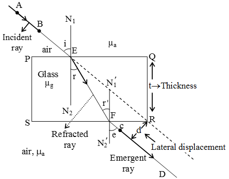 (Image: Light ray incident on a parallel-sided glass slab, showing incident angle i, refracted angle r, and emergent ray parallel to incident but laterally shifted.)
When light passes through a parallel-sided glass slab, it emerges parallel to its original direction but is laterally displaced ().
If is the thickness of the slab, is angle of incidence, is angle of refraction inside slab:
From geometry, and . So .
For small angles and (so ):
. Since for small angles (where is glass, is air ), .
For multiple slabs, the shifts add up if they are simple displacements.
(Image: Light ray incident on a parallel-sided glass slab, showing incident angle i, refracted angle r, and emergent ray parallel to incident but laterally shifted.)
When light passes through a parallel-sided glass slab, it emerges parallel to its original direction but is laterally displaced ().
If is the thickness of the slab, is angle of incidence, is angle of refraction inside slab:
From geometry, and . So .
For small angles and (so ):
. Since for small angles (where is glass, is air ), .
For multiple slabs, the shifts add up if they are simple displacements. -
Refraction through a Prism:
 (Image: Light ray passing through a prism, showing angle of prism A, angles of incidence , refraction , incidence on second face , emergence , and angle of deviation .)
A prism bends light and can also disperse it into colors (like a rainbow!).
Let be the angle of the prism (angle between the two refracting surfaces).
Let be angles at the first surface, and be angles at the second surface (where is internal incidence, is final emergence).
From geometry within the prism: .
The total angle of deviation () between the incident and emergent ray is:
For the angle of minimum deviation ( or ), the path of light is symmetrical: , and .
So, .
And .
The refractive index () of the prism material is then given by Snell's law at minimum deviation:
For a thin prism (small ) and small angles of incidence:
. So .
(since , so ).
(Image: Light ray passing through a prism, showing angle of prism A, angles of incidence , refraction , incidence on second face , emergence , and angle of deviation .)
A prism bends light and can also disperse it into colors (like a rainbow!).
Let be the angle of the prism (angle between the two refracting surfaces).
Let be angles at the first surface, and be angles at the second surface (where is internal incidence, is final emergence).
From geometry within the prism: .
The total angle of deviation () between the incident and emergent ray is:
For the angle of minimum deviation ( or ), the path of light is symmetrical: , and .
So, .
And .
The refractive index () of the prism material is then given by Snell's law at minimum deviation:
For a thin prism (small ) and small angles of incidence:
. So .
(since , so ).
Part 2: Wave Optics – Light Shows Its Wavy Side!
Ray optics is great, but it doesn't tell the whole story. Light is also an electromagnetic wave, and this wave nature leads to some truly beautiful and bizarre phenomena!
Nature's Light Show: Interference in Thin Films पतली फिल्म
When light waves from different paths meet up, they can interfere.
- Constructive Interference: Waves align crest-to-crest, reinforcing each other (brighter light).
- Destructive Interference: Waves align crest-to-trough, canceling each other out (dimmer light or darkness).
Thin Film Interference (Soap Bubbles, Oil Slicks): This creates the shimmering colors you see on soap bubbles or oil films on water. Light reflects from both the top and bottom surfaces of the thin film. These two reflected waves can interfere. The condition for interference depends on:
- The thickness of the film ().
- The refractive index of the film ().
- The angle of incidence/refraction ( inside the film).
- The wavelength of light ().
- Phase changes on reflection: A crucial point! When light reflects from the boundary of a medium with a higher refractive index, it undergoes a phase shift (equivalent to an extra path difference of ). Reflection from a rarer medium has no phase shift.
Let's assume light in air reflects from a film of index on a substrate.
- Reflection from top surface (air-film): Phase change if .
- Reflection from bottom surface (film-substrate): Phase change if .
Considering a film of thickness , refractive index , with light incident nearly normally ( for simplicity, or keep for generality) and the phase change:
-
For Constructive Interference (Bright fringe) in Reflected Light: The optical path difference (OPD = ) plus any net phase shift effects must be an integer multiple of . If one reflection has a phase shift and the other doesn't (most common case, e.g., air-film-air or air-film-glass where and or vice-versa for one of them):
-
For Destructive Interference (Dark fringe) in Reflected Light:
-
For Transmitted Light: The conditions are typically reversed because there's no relative phase shift difference between the directly transmitted ray and the twice-reflected-then-transmitted ray that interferes with it (either both internal reflections have phase shifts or neither does, or phase shifts at external surfaces don't play same role).
- Constructive (Max intensity):
- Destructive (Min intensity):
Newton's Rings: The Bullseye Pattern!
When a plano-convex lens (one flat side, one curved) is placed on a flat glass plate, a thin air film of varying thickness is formed between them. When illuminated from above with monochromatic light, a pattern of concentric bright and dark rings – Newton's Rings – is observed due to interference between light reflected from the bottom of the lens and the top of the glass plate. The radius () of the dark ring (for destructive interference, assuming nearly normal incidence, air film , phase change at bottom reflection): . From geometry of a lens with radius of curvature and air film thickness : . For small , is negligible, so . Thus . So, .
Michelson Interferometer: Precision Measurement Magic!
This brilliant device, invented by Albert Michelson, splits a beam of light into two perpendicular paths using a beam splitter. These beams reflect off mirrors at the ends of the "arms" and are then recombined. If there's any difference in the path lengths traveled by the two beams, they will interfere, creating a pattern of fringes. By carefully moving one of the mirrors by a tiny amount, the fringe pattern shifts. Counting these shifts allows for incredibly precise measurements of distance (or wavelengths of light). It was famously used in the Michelson-Morley experiment to try (and fail) to detect the "luminiferous aether."
Unveiling the Hidden: Diffraction and Gratings
Light doesn't always travel in perfectly straight lines, especially when it encounters obstacles or narrow openings. It tends to bend around edges – this is diffraction. It's another hallmark of light's wave nature.
Diffraction by a Single Slit: Spreading Out the Light
When light passes through a narrow slit (comparable in size to its wavelength), it spreads out into a pattern of a central bright band flanked by dimmer, alternating dark and bright fringes. The intensity () of the diffracted light at an angle from the central axis is given by: Where:
- is the intensity at the center ().
- .
- is the width of the slit.
- is the wavelength of light.
The minima (dark fringes) occur when (but ), which means for . So, . The condition for the minimum is: The first minimum is at .
Plane Diffraction Grating: Many Slits Make Cool Patterns!
A diffraction grating is an optical component with a periodic structure that splits and diffracts light into several beams travelling in different directions. Typically, it consists of a large number of equally spaced parallel slits or grooves. When light passes through a grating, each slit acts as a source of diffracted waves. These waves interfere with each other, producing a sharp interference pattern. The intensity () of the diffracted light at an angle from a grating with slits, slit width , and slit spacing (center-to-center) is: Where:
- (single-slit diffraction factor).
- (multi-slit interference factor).
Key features of the pattern:
- Principal Maxima (Brightest Fringes): Occur when the path difference between waves from adjacent slits is an integer multiple of the wavelength, leading to strong constructive interference. This happens when such that also leads to maximum, effectively when . So, . This is the grating equation. is the order of the maximum.
- Minima: Occur when but . This happens times between principal maxima.
- Secondary Maxima: Smaller peaks between principal maxima, much less intense.
Absent Spectra (Missing Orders): Sometimes, a principal maximum predicted by might be missing! This happens if that angle also corresponds to a minimum of the single-slit diffraction pattern (, where is an integer ). If the width of the opaque part () of the grating equals the width of the transparent slit (), so . Then the condition for single-slit minima is . The condition for grating maxima is . If , or , then an order (which is an even multiple of ) will be missing if . For example, if , the orders of principal maxima might be absent. Condition for absent spectra for even diffraction orders (m = 2, 4, 6, ...) can be expressed as . (Here is opaque part). If , then . Then for a principal maximum, . For a single-slit minimum, . If . So, when is an even number (and is an integer ), that order is missing. This is correct.
Grating Power: Resolving and Dispersing Light!
How good is a grating at its job? Two key metrics:
-
Dispersive Power (): Spreading Out the Colors! This measures how well a grating separates different wavelengths angularly. It's the rate of change of diffraction angle with respect to wavelength . From , differentiate with respect to (keeping constant): . Angular dispersion: Higher means greater angular separation for a given wavelength difference.
-
Resolving Power (): Seeing Fine Details! This measures a grating's ability to distinguish between two very closely spaced wavelengths. It's defined as: Where is the minimum wavelength difference that can just be resolved at wavelength . For a grating, the resolving power is given by: Where:
- is the total number of illuminated slits (or lines) on the grating.
- is the spectral order of the maximum being used.
Higher and higher order mean better resolving power – you can see finer spectral details!
Key Takeaways: Your Optics Pocket Illumination!
Wow, light sure knows how to put on a show! From straight-line rays to complex wave interactions, here's the essence of its optical repertoire:
-
Ray Optics Basics:
- Reflection: Light bounces! Laws: angle of incidence = angle of reflection. Mirrors use this.
- Mirror Equation: (with sign conventions!) relates object (), image (), and focal length (). Magnification .
- Refraction: Light bends when changing media! Snell's Law () governs the bend. Refractive index () is key. Total Internal Reflection happens beyond the critical angle.
- Lenses: Use refraction to form images. Lens Maker's Formula and Thin Lens Equation () are your friends. Prisms use refraction for deviation and dispersion.
-
Wave Optics Wonders:
- Interference: Waves combine! Constructive (brighter) or destructive (dimmer). Seen in thin films (colors depend on and phase shifts) and Newton's Rings. Michelson interferometer uses it for precision.
- Diffraction: Light bends around edges/openings. Single slits produce a central bright band with side fringes ( for minima).
- Diffraction Gratings: Many slits create sharp interference patterns ( for principal maxima). They are used for separating wavelengths (spectroscopy).
- Grating Performance: Dispersive power () tells how well colors are spread. Resolving power () tells how well close wavelengths can be distinguished.
Optics is a beautiful blend of geometry and wave physics, explaining how we perceive the universe and enabling technologies that range from eyeglasses to the internet. The journey of light is full of fascinating twists and turns! Keep looking, keep wondering!